Arduino Measures 20V Signals Using Quantizer


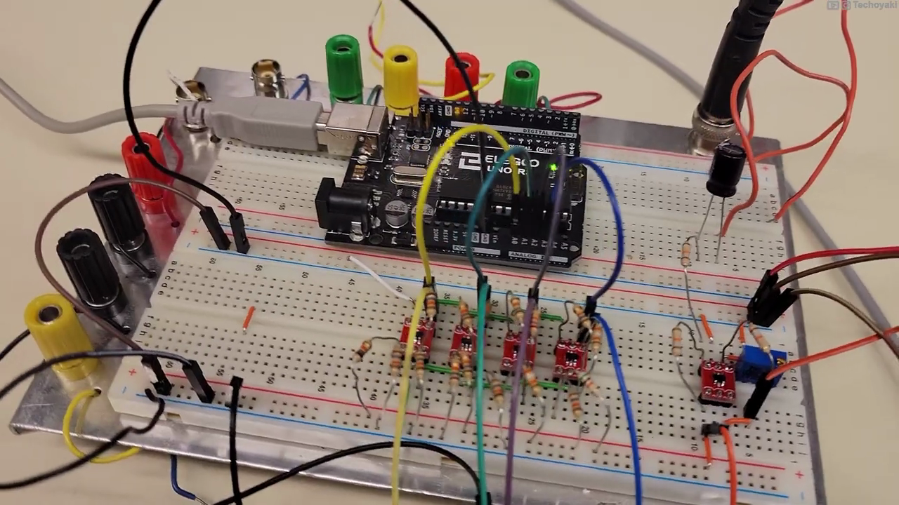
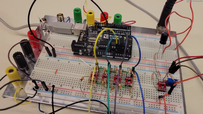
Canadian electronics geek and nascent YouTuber [Technoyaki] wanted to measure 20 volt signals on his Arduino. One might typically use a voltage divider to knock them down to the 5 volt range of the Arduino’s 10-bit A/Ds. But he isn’t one to take the conventional approach. Instead of using two resistors, [Technoyaki] decides to build an analog circuit out of sixteen resistors, four op amps and a separate 6 VDC supply.

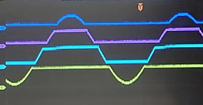
What is a quantizer? In the usual sense, a quantizer transforms an analog signal (with an infinity of possible values) to a smaller (and finite) set of digital values. An A/D converter is a perfect example of a quantizer. [Technoyaki], stretching the definition slightly, and uses the term to describe his circuit, which is basically a voltage slicer. It breaks up the 20 V signal into four separate 5 V bands. Of course, one could almost accomplish this by just using an Arduino Due, which has a 12-bit A/D converter (almost, because it has a lower reference voltage of 3.3 V). But that wouldn’t be as much fun.
Why use all these extra components? Clearly, reducing parts count and circuit complexity was not one of [Technoyaki]’s goals. As he describes it, the reason is to avoid the loss of A/D resolution inherent with the traditional voltage divider. As a matter of semantics, we’d like to point out that no bits of resolution are lost when using a divider — it’s more accurate to say that you gain bits of resolution when using a circuit like the quantizer. And not surprising for precision analog circuitry, [Technoyaki] notes that there are yet a few issues yet to be solved. Even if this circuit ultimately proves impractical, it’s a neat concept to explore. Check out the video below the break, where he does a great job explaining the design and his experiments.
Even though this isn’t quite a cut-and-paste circuit solution at present, it does show another way to handle large signals and pick up some bits of resolution at the same time. We wrote before about similar methods for doubling the A/D resolution of the Arduino. Let us know if you have any techniques for measuring higher voltages and/or increasing the resolution of your A/D converters.
Continue Reading